
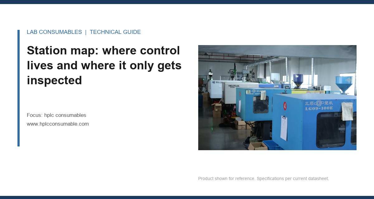
A lot of 40,000 septa came off the line reading 41.8 Shore A on the incoming durometer check, inside the 40 ± 5 spec, and still failed at the customer’s autosampler with core push-through at 96 punctures instead of the 150 the qualification run had promised. The durometer was fine. The problem was that the 90-second post-mold cure had been trimmed to 55 seconds on the night shift, and nobody on the line was measuring crosslink density. That is the difference between a factory that controls a parameter and a factory that checks a part.
So let me answer the question directly: how HPLC consumables are manufactured and what the factory actually controls comes down to a station map where some parameters are closed-loop (the machine corrects itself) and others are open-loop (someone checks at the end and hopes). Knowing which is which tells you what a certificate of analysis is really worth.
I have walked maybe a dozen consumable plants across the US, Germany, and China. They all run the same rough sequence for vials, caps, septa, and column hardware: incoming material, molding or machining, assembly, cleaning, packaging, final inspection. The differences that matter are not the machines. They are which stations have a feedback loop and which are pass/fail gates at the end.
Here is the map I use when I audit a supplier. It is not a QC sampling plan (that is a separate discipline). It is a control architecture question.
| Station | Key parameter | Control mode | Typical spec / target |
|---|---|---|---|
| Resin / glass incoming | Melt flow index, hydrolytic class | Inspection only (CoA + spot check) | MFI ±0.3; USP Type I borosilicate |
| Injection molding (vials) | Mold temp, cavity pressure, cycle time | Closed-loop (cavity pressure) | Mold 95–110 °C; cavity pressure ±2% |
| Compression molding (septa) | Press temp, cure time, crosslink density | Open-loop on cure, closed-loop on temp | Cure ≥90 s; durometer 40–50 Shore A |
| Machining (column hardware) | Bore diameter, thread pitch, surface finish | Closed-loop on position (CNC) | Bore ±0.02 mm; 10-32 UNF thread |
| Assembly (cap + septum) | Seating force, torque, concentricity | Open-loop (force monitored, not corrected) | Cap torque 0.6–0.9 N·m; concentricity ≤0.15 mm |
| Cleaning | Particulate count, extractables | Inspection only (batch release) | ≤5 particles >10 µm per vial |
| Packaging | Bag seal integrity, count accuracy | Closed-loop on count, open-loop on seal | Seal 145 °C / 1.2 s; ±0.5% count |
| Final inspection | Dimensions, visual, functional | Inspection only | AQL 0.65 per ISO 2859-1 |
Read that table carefully. The stations where defects are born (compression cure, assembly seating, cleaning) are mostly open-loop. The stations that are tightly closed-loop (molding, machining) are the ones where defects are rare. That asymmetry is the whole story of consumable quality problems.
The molding station controls cavity pressure, not just dimensions
Injection molding of 2 mL vials looks simple until you realize that the cavity pressure profile is what determines whether the vial neck stays round and whether the bottom is stress-free. A 32-cavity tool on a 90-ton press can drift 0.05 mm on neck diameter within a single shot if the gate freezes unevenly. Good plants monitor cavity pressure per cavity and adjust hold pressure on the fly. Cheap plants measure the finished vial with calipers at the end of the shift.
Why does neck roundness matter? Because the cap has to seat concentrically, and a 0.1 mm ovality on a 9 mm neck translates to a cap that rocks. That rocking cap is the one that leaks at 4 °C on the autosampler tray after 8 hours. I have seen a customer chase a “septa problem” for three weeks when the real issue was a worn cavity insert producing 0.12 mm ovality on one cavity out of 32. The septa were innocent. The vial was out of round.
What the factory should be controlling here, and what you should ask about:
- Cavity pressure closed-loop on every cavity, not just the master. Look for a trend chart, not a pass/fail printout.
- Mold temperature zones held to ±3 °C. A cold zone on one side of the tool produces short shots you will only catch at AQL inspection.
- Cycle time consistency to ±0.5 s. Variability here shows up as weight variation, which shows up as dimensional drift.
- Resin lot traceability to the shot. If they cannot tell you which resin lot made which vial lot, they are not controlling the input.
If you are sourcing vials, the question to ask is not “what is your tolerance” but “what is your cavity pressure control bandwidth and do you trend it per cavity.” The answer separates a real factory from a repackager. For a deeper look at how vial geometry interacts with autosampler behavior, the OEM vial resource covers the dimensional side.
Compression cure is the open-loop station that fails quietly
Septa are compression molded silicone or silicone/PTFE laminate, and the parameter that governs puncture life is crosslink density. Crosslink density is set by cure temperature and cure time. Temperature is usually closed-loop on the press. Time is often not, because the operator loads a batch, starts a timer, and moves on. If the timer is trimmed to hit a shift target, the septa look fine, pass durometer, and fail at puncture.
The physics: under-cured silicone has lower tear strength and higher compression set. A septum that should survive 150 punctures at 22 gauge will core or tear at 90. The durometer can still be in spec because durometer measures hardness, not network completeness. I have personally seen a lot measure 44 Shore A on the bench and fail at 96 punctures on the autosampler. The fix was not a new durometer. It was a solvent swell test (toluene uptake over 24 h) added as a cure proxy, plus a hard interlock on the press timer that logged every batch.
What a factory that controls this station does:
- Interlocks the press timer so the mold cannot open early. No override, no shift workaround.
- Runs a crosslink proxy per batch: solvent swell, or a tear-strength pull, not just durometer.
- Tracks compression set at 22 h / 175 °C per ASTM D395, Method B, target ≤25%.
- Holds cure temperature to ±2 °C and logs it, because a 5 °C drop adds roughly 30% to required cure time.
The temperature rating of the finished septum matters too. Standard silicone is good to about 200 °C continuous; if the customer is running high-temperature GC or a hot autosampler, the spec has to say so. For a fuller treatment of how the puncture actually behaves mechanically, see the septa article on this site; here the point is narrower: the cure timer is the control point, and it is usually open-loop.
Assembly torque and seating force decide whether the cap seals
Once the cap and septum are mated, the assembly station is where a lot of latent leaks are created. Two parameters matter: seating force (how hard the septum is pressed into the cap) and cap torque (how hard the cap is turned onto the vial). A crimp cap and a screw cap behave differently, but both have a window.
For 11 mm crimp caps, the crimping force is typically 0.4–0.6 kN, and the crimp height should land at 5.9–6.1 mm. Too little and the seal is incomplete; too much and you deform the septum, which reduces puncture life and can create a channel. For 9 mm screw caps, torque is usually 0.6–0.9 N·m; below 0.5 N·m you get leaks at 4 °C, above 1.1 N·m you can crack the neck or extrude the septum.
Here is the control problem. Most assembly lines monitor seating force but do not close the loop on it. They log the force, flag out-of-range parts, and keep running. The torque on screw caps is often set once at changeover and never re-verified mid-run. That is an open-loop station wearing a closed-loop costume.
What to look for:
- Torque verification every 500 caps with a calibrated torque tester, logged, not just at setup.
- Seating force closed-loop with automatic rejection, not just alarm.
- Concentricity check ≤0.15 mm between cap and vial axis. Off-axis caps leak under centrifuge or vibration.
- Crimp height measured per batch against the 5.9–6.1 mm window for 11 mm caps.
I had a case where a customer’s 9 mm screw-cap lots started leaking at 4 °C after six months of clean running. The measurement that found it: torque on 30 caps from three lots. Two lots read 0.72 N·m. One lot read 0.48 N·m. The assembly line’s torque head had drifted after a tooling change and nobody re-verified. The fix was a mid-run torque check every 500 caps plus a daily calibration against a reference cap. The septa and vials were fine the whole time. The vial closures reference covers the closure geometry side of this.
Column hardware: bore, thread, and surface finish are machined, not molded
For columns and fittings, the factory controls different things. The tube bore is typically machined or drawn to ±0.02 mm, and the end fitting thread is 10-32 UNF with a specified pitch diameter. The surface finish inside the bore matters because roughness creates peak tailing for basic analytes. A Ra above 0.4 µm inside the bore will show up as a tailing factor above 1.5 on a USP tailing check for a probe like pyridine.
The control here is mostly closed-loop on the CNC (position feedback), but the surface finish is often only inspected at the end. That is a gap. If the tool wears, Ra climbs, and the first sign is a customer’s tailing factor drifting. A factory that controls this runs a profilometer check on the first part of each tool-change cycle and tracks tool life in parts, not hours.
Packing is the other half. Slurry packing pressure and flow rate determine bed uniformity. A bed with a 5% void at the inlet will show as a plate count drop of 20–30% on the first injection. Good plants run a test injection on every packed bed and reject out-of-spec beds before they ship. That is a closed-loop at the end of the line, which is the right place for it.
Cleaning and packaging: the stations nobody watches
Cleaning is where particulate and extractables are controlled, and it is almost always inspection-only. A vial that looks clean can carry 10 to 20 particles above 10 µm if the rinse water loop is contaminated or the drying tunnel is dirty. The control is a particulate count per batch (target ≤5 particles >10 µm per vial by light obscuration) and an extractables screen by LC-MS on a representative vial per lot.
Packaging seal integrity is the other sleeper. A bag seal at 145 °C for 1.2 s is typical, but if the seal bar drifts 10 °C cold, you get a channel that lets humidity in. Silicone septa absorb moisture, and a wet septum in a GC inlet produces a ghost peak and a noisy baseline. The control is a dye penetration test on a sample of bags per shift, plus a desiccant check. Few factories do this. Ask.
Troubleshooting checklist: which station to blame
When a lot fails in the field, the symptom points to a station. Use this to narrow it before you blame the supplier.
- Core push-through or low puncture count: compression cure station. Check solvent swell and compression set, not durometer.
- Leaks at 4 °C after hours on tray: assembly torque or cap concentricity. Measure torque on 30 caps across three lots.
- Tailing factor drift on basic analytes: column bore surface finish or packing uniformity. Check Ra and run a plate count.
- Ghost peaks and baseline noise: packaging seal or drying. Check bag seal integrity and septum moisture.
- Autosampler needle bending: vial neck ovality or cap seating. Measure neck diameter across cavities.
- Particulate in blank injections: cleaning station. Run a light obscuration count on the vial lot.
Two field cases in one article is enough, but I will add a third briefly because it is instructive. A customer reported intermittent needle bends on a 96-well autosampler. The measurement: neck ovality on 50 vials from one lot. One cavity read 0.14 mm ovality against a 0.10 mm limit. The fix was a cavity insert change and a per-cavity ovality check on the first part of each shift. The septa and caps were never the problem.
What the certificate of analysis actually tells you
A CoA is a record of final inspection, not a record of control. If the factory only checks at the end, the CoA tells you the lot passed the gate. It does not tell you the cure timer was interlocks, the torque head was calibrated mid-run, or the cavity pressure was trended. Those are the parameters that predict whether the next lot fails.
When I qualify a supplier, I ask for four things beyond the CoA: the cavity pressure trend for the lot, the cure time log with interlock status, the torque verification record at 500-cap intervals, and the bag seal dye test per shift. A factory that controls its line can produce all four in an hour. A factory that inspects at the end cannot. That is the decision rule.
The reference standards to anchor the conversation: U.S. EPA SW-846 for method-driven performance, USP <621> for chromatographic system suitability (tailing, plate count, resolution), and ISO 2859-1 for the AQL gates. For vendor technical data, the Agilent consumables, Thermo Fisher sample handling, and Restek libraries are useful for cross-checking specs against your own requirements.
If you are building a sourcing file, start from the station map, not the catalog. The HPLC consumables range and the chromatography supplier directory are reasonable starting points for part numbers, but the audit questions above are what separate a controlled line from an inspected one.
The decision rule is simple: buy from the factory that can show you a closed-loop trend for cavity pressure and a logged cure interlock, and treat every other parameter as a check you have to do yourself. The CoA is the last gate, not the first control. If the supplier cannot tell you which stations are closed-loop and which are inspection-only, they have not mapped their own line, and you are the one who will find out where the open loops are.
References & further reading
Related resources from our lab consumables network:
- Hplc Consumables at hplcconsumable.com
- Chromatography Supplier at chromatographysupplier.com
- Oem Vial at oemsamplevials.com
- Vial Closures at vialclosures.com
External references and standards: